QUALITY & VERIFICATION

Quality starts with what can be defined and checked.

Verification of a micro-perforated component is not limited to a nominal aperture or an outside dimension. Aperture geometry, surface condition, component form and system interface are considered together against the technical requirement.

The control scope is defined against the technical requirement. The production result is verified on the component.

CONTROL AREAS

Four areas define the verification scope.

The component is evaluated as a complete technical part rather than through an isolated hole diameter.

01

Aperture geometry

The target aperture is considered together with the geometry produced on the working and back faces. For tapered micro-holes, the two faces are not treated as interchangeable dimensions.

  • Nominal aperture
  • ØA · Inlet / working-face aperture
  • ØB · Outlet / back-face aperture
  • Tapered geometry
02

Surface condition

Burr condition and laser-process residue form part of production control and can influence the required post-processing approach.

  • Burr condition
  • Process residue
  • Working face
03

Component form

Micro-perforation is not evaluated independently from the complete part. Thickness, overall geometry and component form remain relevant after laser processing.

  • Overall geometry
  • Thickness
  • Component form
04

System interface

Centre, perimeter, mounting and indexing features are considered in relation to the existing component or equipment interface.

  • Centre geometry
  • Perimeter geometry
  • Mounting / indexing
  • Equipment context

TYPICAL PRODUCTION & VERIFICATION FLOW

  1. 01 Technical requirement
  2. 02 Test perforation · where required
  3. 03 Process setup
  4. 04 Production
  5. 05 Cleaning & form stabilisation
  6. 06 Final verification
  7. 07 Marking & shipment preparation

BEFORE THE FULL COMPONENT

The produced geometry is checked before full-part production.

Where required, test perforations are produced before the complete component is processed. Working- and back-face aperture geometry and surface condition provide direct feedback before full-part production.

DEFINE

Required geometry

Establish the geometry and technical features relevant to the application.

INSPECT

Produced condition

Inspect the working face, back face and resulting surface condition.

REFINE

Production approach

Use the inspected result to refine the approach before processing the full component.

Process parameters guide production; verification is based on the measurable and observable result achieved on the component.

GEOMETRY & MEASUREMENT

Geometric definition extends beyond a single aperture value.

The schematic identifies features that can enter the measurement or geometric-control scope according to the technical requirement. It is a terminology diagram, not a measured component record.

Aperture cross-section

Cross-section of a tapered aperture EMC schematic convention: ØA is the narrower inlet / working-face aperture and ØB is the wider outlet / back-face aperture. T marks material thickness; α shows the wall angle relative to the surface normal. ØA ØB T α
ØA
Inlet / working-face aperture
ØB
Outlet / back-face aperture
T
Material thickness
α
Taper

Top view

Hole pitch in top view P indicates the centre-to-centre distance between two adjacent holes in an illustrative array. P
P
Hole pitch (top view)
Schematic representation · not to scale.

OPTICAL CONTROL

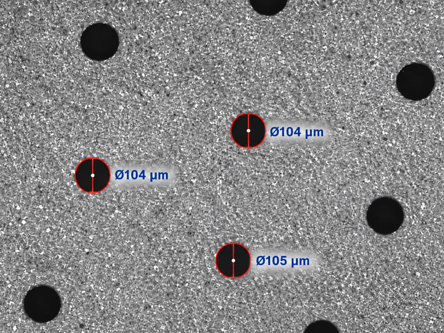
The production result is checked under a microscope.

A microscope image taken from production is used to evaluate aperture geometry and surface condition.

Optical microscope image of a micro-perforated metal surface
Optical microscope image from production · Representative inspection view

Where relevant to the project, open-area percentage can also be derived geometrically from the defined perforation pattern.

CONTROL METHODS

The control method is defined by the technical requirement.

The control method, control scope and acceptance criteria are defined against the technical reference established for the project. That reference may be a drawing, defined geometry or, where appropriate, verified information obtained from an existing component.

Feature Control method Control stage Control output
ØA · Inlet / working-face aperture Sampled measurement using an optical microscope with self-calibration capability. Test perforation and final control Measurement result
ØB · Outlet / back-face aperture Sampled measurement using an optical microscope with self-calibration capability. Test perforation and final control Measurement result
ØA–ØB face geometry / taper Working- and back-face aperture geometry are reviewed together. Test perforation and final verification Geometric comparison
Hole geometry Shape and aperture are reviewed using an optical microscope. Test perforation and final control Optical inspection
Hole pattern / pitch Optical and geometric control is performed according to the technical requirement. Production and final control where required Geometric control
Burr / surface condition Surface condition is reviewed using an optical microscope and visual inspection. After cleaning and during final control Optical / visual inspection
Component form Component geometry is compared against the drawing and application requirement. After form stabilisation / correction Geometric conformity check
System interface / critical dimensions Critical features are compared against the drawing or existing-component reference. Final control Comparison against technical reference

Optical dimensional verification is performed using an optical microscope with self-calibration capability. Before each part or job, the production machine is recalibrated to keep the requested hole dimensions under control during production. Verification results can be shared as technical documentation according to project requirements.

VERIFICATION PRINCIPLES

The control scope follows four practical principles.

Control follows the technical reference

The applicable control scope and acceptance criteria are defined against the technical reference established for the project.

A nominal aperture does not define the full scope

Working- and back-face geometry, surface condition, component form and other project-critical features can also enter the control scope.

Compatibility is checked through the relevant interface geometry

Equipment compatibility can depend on centre, perimeter, mounting and indexing geometry in addition to overall diameter.

Control scope follows the component structure

The perforated area, hole count and distribution across the component influence the control scope. As the hole count or perforated area increases, the number of controlled regions and measurement points is increased. Aperture geometry and surface condition are reviewed across different regions to evaluate the production result.

TECHNICAL CONTACT

Let’s discuss your verification requirements.

A machine or system reference or basic application information is enough to start. An existing component or drawing can support the review where available; we’ll clarify the applicable control scope together.

Useful starting information

  • Application requirement
  • Machine / system reference
  • Existing component / drawing — if available